Home Assistant media folder – connect to SMB share

Ooof. This one kicked my ass for a really long time. The question is “How to connect the Home Assistant Media folder to an SMB share?” There’s a wizard, but what to enter for the Remote share entry is murky.

A part of this is pretty obvious, but the other part is not. Of course, I tried the wizard first, but I didn’t enter the Remote share entry correctly. I tried reading the documentation, but it wasn’t much more than “For the Remote share entry, put in the remote share.” Home Assistant would always fail to mount the share, and the error message was (essentially) “It didn’t work”. Sigh.

I had previously created an SMB share on my Synology NAS, and could map to it just fine from my main Linux desktop, from my Nextcloud instance, and from Windows machines I have here on my home network. I knew from my Nextcloud install (adding it to /etc/fstab) that the vers=3.0 option was important.

Doing a search found a Youtube video about editing the /config/configuration.yaml file and running a shell command. It mentioned that the vers=3.0 was important. Maybe this is what I need? This turned out to be a rabbit hole (but no rodent with a mean streak a mile wide at the end 1).

Since the system-launched shell command wasn’t working, I tried the next logical step: try it from an actual command line. It didn’t work. I think that is because of Docker and the impermanence of the terminal shell and sandbox for security.

I installed a terminal app in Home Assistant, but whenever I tried the same mount command that worked on Linux, it would fail on Home Assistant with “permission denied”. Not really helpful. In fact, it seems unhelpful, because if I read between the lines 2 I see “your password is wrong” – which it wasn’t. “Permission denied” is the error message you get when your password expires, and the credentials file has the old password. Of course, I knew my password was correct: but if I were someone brand new to this, I would have been mislead by my own thinking.

Here is the mount command that does work in Linux but not in Home Assistant:

mount -t cifs -o vers=3.0,credentials=/config/.smbcredentials //mysynology.domain.tld/sharename_smb/data /media/nasfiles 3 4

The problem that I was running into was that the Home Assistant documentation never tells you what it wants for “Remote share”. The dialog box says “This is the name of the share on your storage server” – but that doesn’t help, because it doesn’t specify what to put in. That’s why I’m writing this post: if you have a mount command that does work elsewhere, the pieces you need are here.

Over on the Synology, it told me the share name was smb://mysynology.domain.tld/sharename_smb/data

That does not work here in Home Assistant.

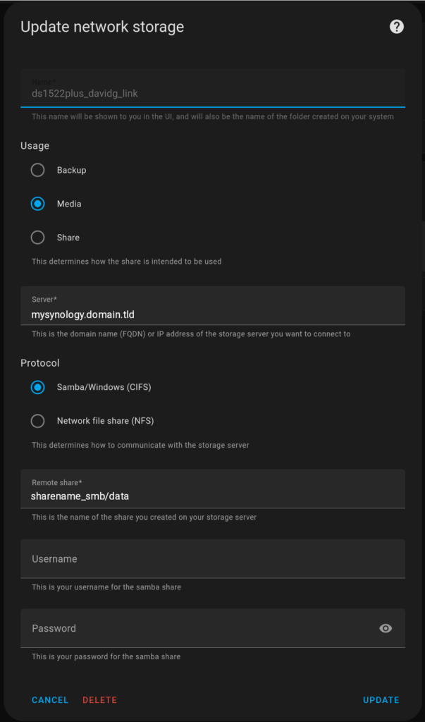
Here are the settings that do work:

So, from the mount command above, the Server entry is mysynology.domain.tld and the Remote share entry is sharename_smb/data

Phew. This was a long time in figuring out, as I tried all sorts of stuff for the Remote share entry:

  • /sharename_smb/data 5
  • mysynology.domain.tld/sharename_smb/data
  • //mysynology.domain.tld/sharename_smb/data
  • mysynology/sharename_smb/data
  • smb://mysynology.domain.tld/sharename_smb/data
  • \\mysynology.domain.tld\sharename_smb\data
  • \\sharename_smb\data
  • \\\\sharename_smb\\data
  • sharename_smb
  • data ( with the Server being mysynology.domain.tld/sharename_smb )

Hopefully, if you found this post, it helps:

Server entry is mysynology.domain.tld

Remote share entry is sharename_smb/data

  1. Thank goodness it wasn’t the Rabbit of Caerbannog ↩︎
  2. which is a bad idea. ↩︎
  3. host name and share name changed to protect the innocent. Not that any of this is on the public Internet, but why tempt the random bored teenager? They can be pretty clever and persistent. ↩︎
  4. Yes, I had to create a directory named config off the root of my Linux box and copy the .smbcredentials file to it for the mount command to be an exact replica of what would have gone in the shell command in /config/configuration.yaml ↩︎
  5. so close. ↩︎

Trendnet EdgeSmart switch VLAN configuration – set one port on a different VLAN

This was difficult, so I will provide a How-To here. The goal was to put port 8 on my switch on VLAN 4084. This is my Internet of Things (IoT) VLAN.

A prerequisite of course, is that the downlink from the router to the switch has the VLAN 4084 tag in it. For me, that will be port 1 on the switch.

Another PITA is that the Trendnet EdgeSmart switch self configures to 192.168.10.200 – and that is hard-coded. After you get a machine directly connected to it (with a static IP address), then you can configure the switch to use DHCP to put it on your main LAN. But if you find that you want to factory reset to start over, you’re going to have to go back to the static IP config on 192.168.10.x. The MAC address doesn’t show up in the router until after the DHCP inspired reboot, so you have no idea of what the new web admin interface IP address is. After the switch has rebooted, then you can go in to the DHCP leases and find out what the new IP address is. I don’t know that I would have bothered, except that the laptop I was using has a little smaller screen, and the Trendnet web interface is primitive. I could not get decent screen shots on it because of the primitive web page rendering, so I needed to access it from a bigger screen, which meant making it available on my main LAN, which meant DHCP. But I digress.

What I’m trying to get to:

End result is 802.1q VLAN tagging on downlink port 1 and no tagging on port 8

First step: Modify VLAN ID 1

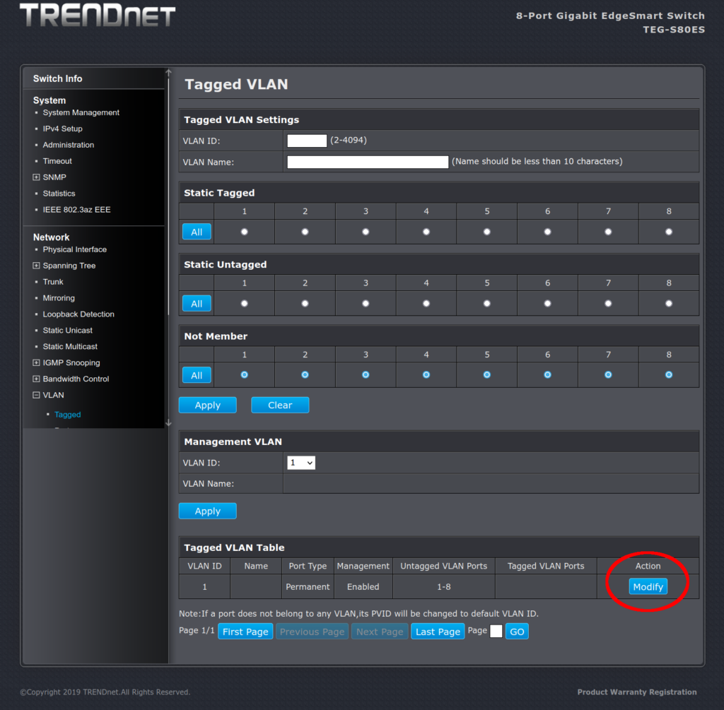
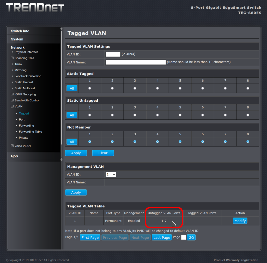
Here is what the web admin page looks like after a factory reset:

After factory reset, you have only VLAN 1 on all ports – but no tagging anywhere

VLAN ID 1 is the default VLAN. But if you never turned on VLANs, it would never have mattered. The default configuration (out of the box) is that if a frame with that VLAN tag were to show up on the switch, all the ports on the switch would strip that tag out (“un” tagging) before putting the frame on the wire of the ports. However, port 8 is a member of VLAN 1. That would cause us trouble later.

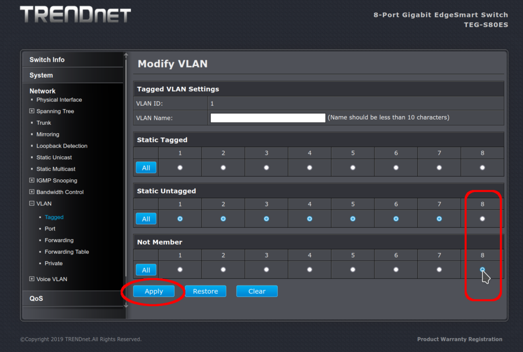
On the VLAN ID 1 modify page, we want to set this:

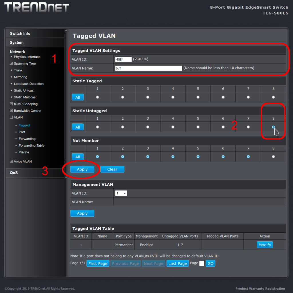
First, on VLAN 1, move port 8 to not-a-member away from static untagged

First, we move VLAN 1 to not-a-member away from static untagged for port 8. Then we apply the change. This will free up port 8 to be assigned a different VLAN later.

What it looks like after:

VLAN ID 1 untagged ports are 1-7 leaving port 8 available

I may be overly sensitive here; but this is a terrible user interface. If I didn’t know better, I would think that the top part (which is really for adding a new VLAN) was telling me the current status of the ports. It is not. But it looks like all the ports are in the not-a-member group. They used a whole bunch of screen real estate to not show me what the actual status is, but what it could be if I were to proceed. I wonder if putting the “Tagged VLAN Table” at the top would be better, and not showing the grid layout of port assignments at all until someone clicked Modify or View.

Second step: adding the new VLAN

Now we can add our VLAN 4084 with port 8 assigned:

On the main web admin screen, create the new VLAN and assign it

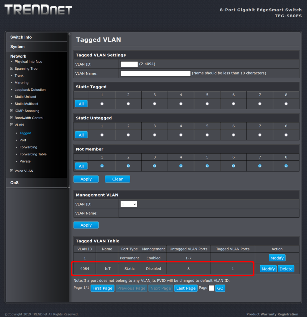
So I typed 4084 into the VLAN ID field, added the descriptive name, then clicked in the Static Untagged section on port 8, and then clicked Apply. This gave me the screen below. Note that we are not done yet.

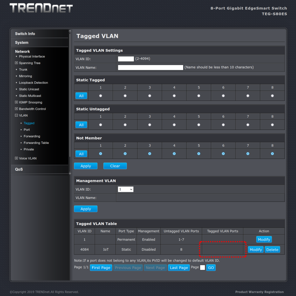
This was the problem: the web interface uses what looks like radio buttons, so the idea that seems to be presented is that clicking on Static Untagged port 8 should move the port from VLAN 1 to VLAN 4084. But attempting to click on port 8: Static Untagged did nothing.

Behind the scene, port 8 was still a member of VLAN 1, so the admin interface would not assign Static Untagged to port 8 in VLAN 4084. It was super frustrating that clicking on port 8 static untagged did nothing: no errors, no warning – just a refusal to work with no response or feedback at all. I could put port 8 in the static tag membership, but those frames would (likely) not be understood by the IoT device. Although the interface showed me the radio button, I could not put port 8 in the Static Untagged membership. A better developed interface would have prompted me with something like “Assigning this port to Untagged will remove VLAN 1”. Okay, do that. Please.

We’re almost there. The configuration will now look like this:

VLAN 4084 is defined and will present on port 8 (once it gets there)

Step 3: add the trunk to the uplink port

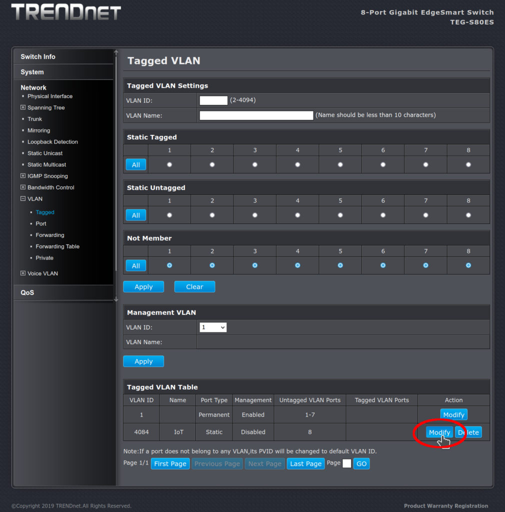
Modify VLAN 4084:

Modify VLAN 4084

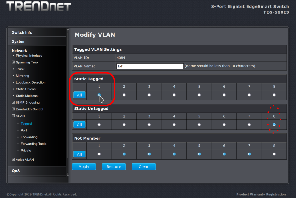
Make the modification: frames to port 1 should be tagged with VLAN 4084. This is because I chose port 1 as the uplink port. The uplink is the trunk connection to the core of the network. But when the switch presents the frame on port 8, the tags should be stripped off (“un” tagged):

VLAN 4084: port 1 tagged, port 8 untagged

Apply our changes, save the configuration, and reboot the device on port 8.

If our VLAN 4084 is otherwise configured correctly, our IoT device should now be on the IoT VLAN. Enjoy.

As painful as this was, I wish I’d bought something else with a better web admin interface than these Trendnet switches. Ultimately, they worked, but man I wasted a lot of hours trying to get them to work. That was four hours of my life I’m not getting back. I should have spent the extra $15 for a switch with software / documentation that doesn’t suck.